Overview #
Some networks have multiple Points of Presence interconnected both internally via inter-datacenter links and externally via multiple transit providers. The diagram below depicts an example diagram with the available routes to one destination on the Internet.
IRP uses the concept of Routing Domains to separate the locations. A Routing Domain’s main characteristic is that its routing tables are mainly built on data received from its locally connected providers and the preferred routes are based on locally defined preferences.
The process of optimizing outbound network traffic in such a configuration is to mainly find better alternative routes locally (within a Routing Domain) and only reroute the traffic to other Routing Domains via inter-datacenter links when local routes are completely underperforming.
It must be noted that a multiple Routing Domain configuration works best if the Points of Presence are not too far away (ex. a network with POPs in San Francisco, Palo Alto and Danville is perfectly suitable under this scenario.
Figure 1.2.6: City wide network
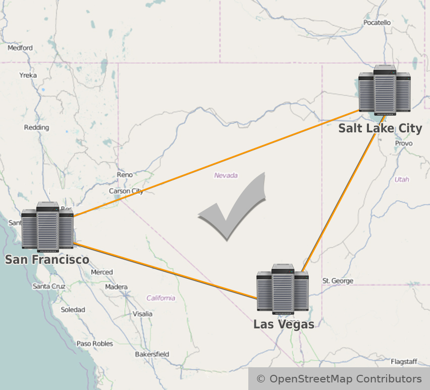
POPs situated at larger distances, for example in Las Vegas and Salt Lake City are still supported by a single IRP instance running in San Francisco.
Figure 1.2.7: Regional network
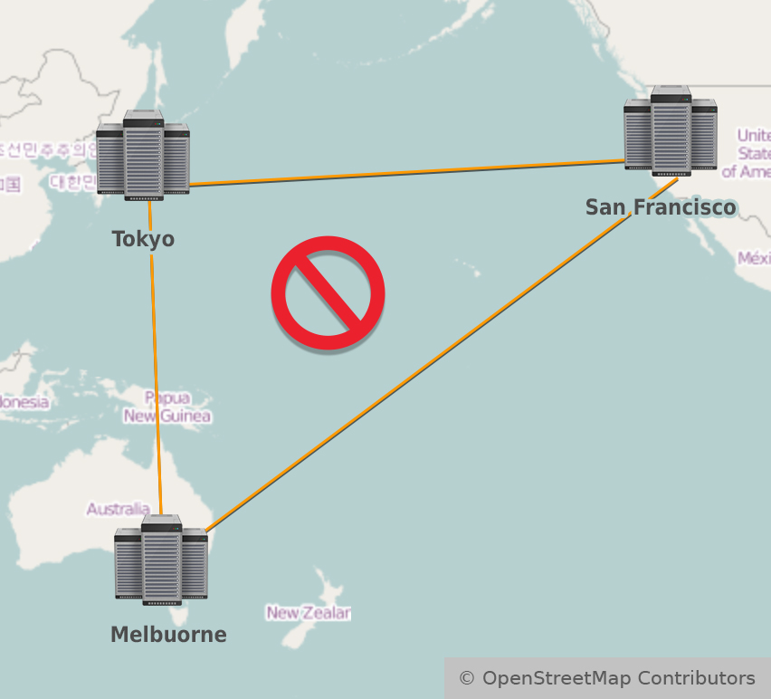
Intercontinental links for POPs in Tokyo and Melbourne are way too far away from the IRP instance in San Francisco and in such a case multiple IRP instances are required.
Figure 1.2.8: Intercontinental network
Multiple Routing Domains implementation attributes. #
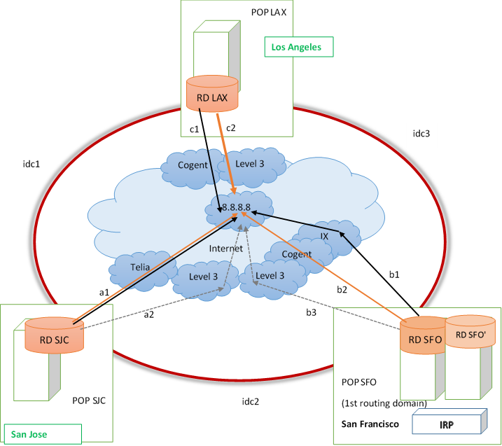
To further detail the multiple routing domain attributes the following diagram will be used:
Figure 1.2.9: Multiple routing domains
-
Multiple locations belonging to the same network (AS) represented in the diagram by POP SJC, POP SFO and POP LAX (of course, more than 3 routing domains are supported).
-
The locations are distinguished by the different Routing Domains within which they operate (de- picted by RD SJC, RD SFO, and RD LAX).
-
The Routing Domains are managed by edge routers belonging to different locations.
-
Nearby locations that process routing data differently should be split into different Routing Do- mains, even if they have the same upstream providers. In the diagram above RD SFO and RD SFO’ are depicted as part of a single Routing Domain. A decision to split or keep in the same routing domain should be made based on exact knowledge on how routing data is processed.
-
Inter-datacenter loop interconnects the different locations (depicted by idc1, idc2 and idc3 seg- ments).
-
Data flows between locations take only the short path (in the example POP SJC can be reached from POP SFO via idc2 path (short) or idc3 + idc1 path (long)).
-
Each Routing Domain has different providers and different preferred routes to reach a specific destination (a1, b1, c1).
-
A single IRP instance collects statistics about traffic (Irpflowd only), probes available destinations and makes improvements towards specific prefixes/networks on the Internet.
-
IRP assumes RTT of zero and unlimited capacity to route traffic within a Routing Domain.
-
IRP assumes that Sites are not physically too far away. It is ok to have different sites in the same city or region as at this scale inter-datacenter links have predictable characteristics. When taking intercontinental links into consideration this is quite probably not the case.
-
Distances between sites (idc1, idc2, idc3 delays) are measured in advance and specified in IRP’s configuration.
Inter-datacenter link characteristics #
Support for Multiple Routing Domains relies on existence of inter-datacenter links. These links should be independent of upstream providers.
Example of inter-datacenter links that multiple routing domains is designed for are:
-
private connections,
-
L2 links with guaranteed service,
-
MPLS links
Constraints #
At the moment IRP multiple Routing Domains implementation does not cover the following:
-
IRP does not take measurements of inter-datacenter link delays (idc1, idc2 and idc3). This values are configurable.
-
IRP does not monitor if inter-datacenter links are operating normally. In case such a link is broken it is expected IRP to loose BGP connectivity with routing domain routers and this will cause IRP improvements to be withdrawn till the link is restored.
-
IRP does not try to detect if the traffic is following long or short paths on the inter-datacenter links. In the image above traffic from RD SJC can follow path idc1 (short) or idc2+idc3 (long). IRP always assumes the short path is being followed internally.
-
IRP does not take measurements of inter-datacenter link capacity and current bandwidth usage. At this stage IRP assumes there is enough inter-datacenter link capacity to also carry the (few) global improvements. Also, IRP tries to minimize usage of inter-datacenter links.
Routing domains #
Routing domain is a generic term used to distinguish a logical location that works with different routing tables. The differences are caused by the fact that a router composes its routing table according to routes received from different providers. It is possible to have multiple routing domains in the same datacenter if routing data is received by different routers (even from same or different sources) and data flows are distributed via different routers by different policies. In the image above RD SFO and RD SFO’ can represent a single routing domain or multiple routing domains depending on what routing policies are applied.
Different routing domains are assigned identifiers in the range 1-100. Routing Domain identifier is assigned individually to each provider via parameter peer.X.rd. It must be noted the Routing domain that hosts the IRP instance is considered as the first routing domain (RD=1).
Parameter global.rd_rtt gives the distances between routing domains. The format of the parameter is
rda:rdb:rtt
for example if RD SJC has Routing Domain id = 42, RD SFO – 1 (since it hosts IRP), RD LAX – 3 then the idc1, idc2 and idc3 rtt is defined as the collection:
global.rd_rtt = 3:42:20 42:1:17 1:3:35
This parameter will be validated for correctness and besides the format above it requires that RD SJC and RD SFO values are different and already configured (RD1 is always present).
$ ping X -c 10 -q
PING X (X) 56(84) bytes of data.
--- X ping statistics ---
10 packets transmitted, 10 received, 0% packet loss, time 9085ms
rtt min/avg/max/mdev = 40.881/41.130/41.308/0.172 ms
Flow agents #
A very natural constraint for Multiple Routing Domain networks is that IRP can rely only on Flow statistics – NetFlow or sFlow.
Flow collector needs to know the exact details of such a configuration in order to correctly determine the overall provider volume and active flows. For this each provider in an MRD setup must be assigned Flow agents to enable IRP to match Flow statistics accordingly. Refer Flow agents for further details.
Global and local improvements #
Local improvements #
Local improvements represent better alternative routes identified within a routing domain. If in the example image above current routes are represented by black lines then local improvements are depicted by orange lines b2 and c2. Keep in mind that a1 just reconfirmed an existing current route and no improvements are made in such a case.
Local improvements are announced in their routing domains and this has the characteristic that local traffic exits customer’s network via local providers. This also means that inter-datacenter interconnects are free from such traffic.
IRP prefers local routes and Improvements to Global improvements.
Parameter bgpd.rd_local_mark specifies a community marker that distinguishes local improvements from Global Improvements. A BGP speaker should not advertise these improvements outside its Routing Domain. It must be noted that a single marker is used for all the routing domains and each of them shall be configured to advertise local improvements within the domain and filter it out for inter-domain exchanges.
Local improvements should be stopped from propagating across routing domains. A route map is used to address this. Below are listed sample route maps for Cisco IOS and JUNOS 9.
Cisco IOS #
neighbor <neighbor-from-another-RD> send-community
(should be configured for all iBGP sessions)

ip community-list standard CL-IRP permit 65535:1
route-map RM-IRP-RD deny 10
match community CL-IRP
route-map RM-IRP-RD permit 20

router bgp AS
neighbor <neighbor-from-another-RD> route-map RM-IRP-RD out
Refer Route-Maps for IP Routing Protocol Redistribution Configuration
JUNOS 9 #
policy-options{
	policy-statement IRP-CL {
		term 0 {
	        from {
	         	protocol bgp;
	         	community IRP-RD;
	        }
	        then reject;
	    }
	    term 1 {
	        then accept;
	    }
	}
	community IRP-RD members 65535:1;
}
protocols {
	bgp {
    	group ebgp {
        	type external;
        	neighbor 10.0.0.1 {
            	export IRP-CL;
        	}
    	}
    }
}
Refer Policy Framework Configuration Guide; Release 9.3
Global improvements #
Global improvements are made when IRP identifies an alternative route that even after factoring in the latencies incurred by inter-datacenter interconnects are better than all existing alternatives. Such an example can be represented by alternative route c2 in the image above. A global improvement is made when one routing domain alternative is better than the best local alternatives in all other routing domains even considering the latencies incurred by inter-datacenter interconnects.In theimage above c2 will become a global improvement if his loss characteristic is best to all alternatives and its latency:
-
(c2+idc1 – margin) is better than best local alternative a1 in RD SJC
-
(c2+idc3 – margin) is better than best local alternative b2 in RD SFO
where:
-
a1, b2 and c2 represent roundtrip times determined by IRP during probing of a destination.
-
idc values are configurable and are set as one entry of global.rd_rtt parameter.
-
margin is given by core.global.worst_ms.
Global improvements move traffic via inter-datacenter interconnects and as such are less desirable to local routes. Global improvements make sense when defined as above and even more sense when packet loss is taken in consideration and routing via a different datacenter reduces packet loss significantly.


