Border Gateway Protocol (BGP) is not merely a protocol—it’s the backbone of the...


Request a personalized demo/review session of our Intelligent Routing Platform

Evaluate Noction IRP, and see how it meets your network optimization challenges

Schedule a one-on-one demonstration of our network traffic analysis product

Test drive NFA today with your own fully featured 30-day free trial
In the last part of our tutorial (view previous part) we will verify that our configuration works properly. Let’s start with the R-NAT router.
As a first step, we are going to check whether NAT is working as expected. The source IP address of traffic going out of the interface Gi0/0 is being translated to an IP address from the NAT pool ISP-A (193.0.1.0/24). Multiple inside local addresses must be translated to a single inside global address as port address translations (PAT) or NAT overload is configured. Issue the ping command multiple times and check the NAT translation table on R-NAT.
R-NAT# ping 193.0.0.13 source GigabitEthernet 0/2
R-NAT# ping 193.0.0.13 source GigabitEthernet 0/2
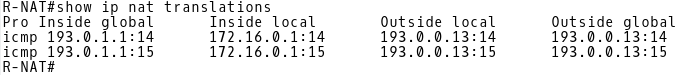
Picture 1: NAT Translation Table when Traffic is Sent out of Gi0/0
The protocol is ICMP and an inside local address 172.16.0.1 is translated to the inside global address 193.0.1.1 (NAT pool ISP-A). Notice the numbers 14 and 15 mapped to the IP address. Those are ICMP identifiers included in the ICMP header of the IP packet (Picture 2). Their map associated ICMP echo requests to echo replies.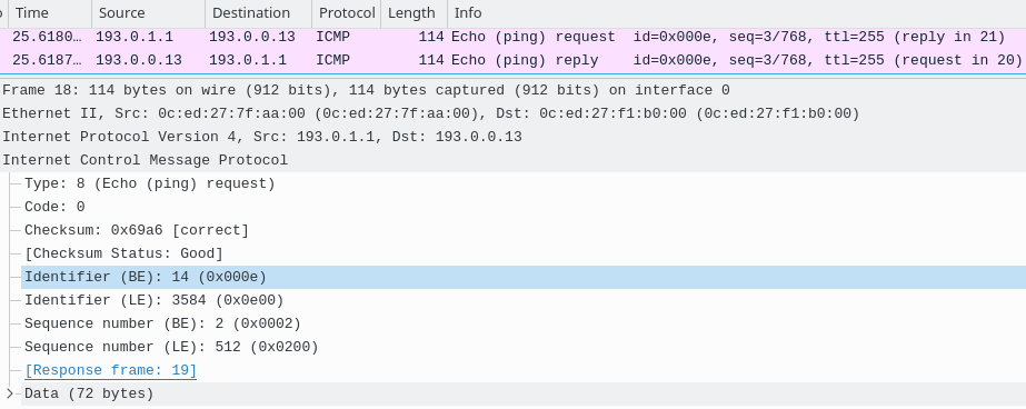
Picture 2: ICMP header of translated IP Packet
Now we will check whether PAT is in use issuing the ping command to 193.0.0.13 from two hosts (172.16.0.100 and 172.16.0.101), connected to the interface Gi0/2 of the R-NAT router. First, let’s delete the NAT translation table of R-NAT.
R-NAT# clear ip nat translation *

Host1$ ping 193.0.0.13
Host2$ ping 193.0.0.13
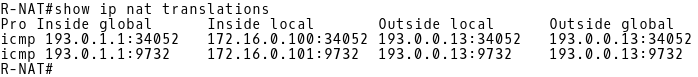
Picture 3: NAT Translation Table when Traffic is Sent out of Gi0/0 from Two Hosts
PAT is in use because the router R-NAT has translated the inside local addresses 172.16.0.100 and 172.16.0.101 to a single inside global address 193.0.1.1 (Picture 3).
It is time to check the NAT translation table when ICMP echo request is sent out of the interface Gi0/1. The inside local address is dynamically mapped to the inside global address 194.0.1.2 when traffic is forwarded out of the Gi0/1. ICMP identifier is 16 inside the ICMP header of the IP packets related to the first ping command (Picture 4). ICMP identifier is 17 for the IP packets related to the second ping command.
R-NAT# clear ip nat translation *
R-NAT# ping 194.0.0.13 source GigabitEthernet 0/2
R-NAT# ping 194.0.0.13 source GigabitEthernet 0/2
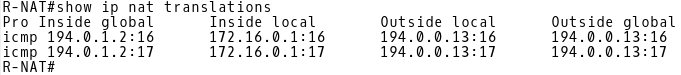
Picture 4: NAT Translation Table when Traffic is Sent out of Gi0/1
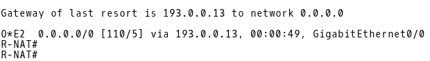
When the link between CE-1 and ISP-A is active, router R-NAT installs OSPF E2 external type route with a route metric 5 received from 193.0.0.13 (R1) into its routing table (Picture 5).
R-NAT# show ip route 0.0.0.0
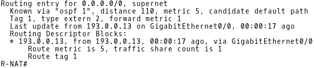
Picture 5: OSPF E2 Route Installed in Routing Table of R-NAT when Link Between CE-1 and ISP-A is Active
Now, check the BGP table on R1. The R1 router learns the default route via iBGP from 193.0.0.5 (CE-1) (Picture 6).
R1# show ip bgp | begin Network
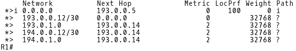
Picture 6: Default Route in BGP Table of R1 Learned via iBGP from CE-1
R2 learns the default route via iBGP from 194.0.0.5 (CE-2) (Picture 7). However, the route is not installed into the routing table of R2 because it is rejected. There is a default route with a better Administrative Distance (AD) 110 received from another source – 194.0.0.14 (R-NAT) learned via OSPF (Picture 8). The AD of iBGP route is 200. Therefore, a default route advertised by R-NAT with a lower AD 110 is installed into the routing table of R2.
R2# show ip bgp | begin Network
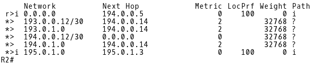
Picture 7: Default Route in BGP Table of R2 Learned via iBGP from CE-2
R2# show ip route ospf
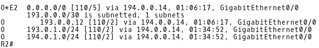
Picture 8: Default Route in Routing Table of R2 Learned from OSPF
R1 is the originator of the default route advertised to R-NAT via OSPF and received by R2. Notice the OSPF router ID 193.0.0.13 (Picture 9).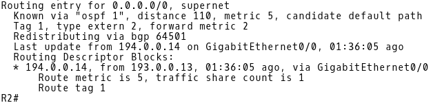
Picture 9: OSPF Router ID 193.0.0.13
The R2 router learns about both NAT prefixes 193.0.1.0/24 and 194.0.1.0/24 from R-NAT via OSPF (Picture 8). OSPF routes are then redistributed to iBGP (Picture 7). The DMZ route 195.0.1.0 is learned via iBGP from DMZ router (195.0.1.3).
Let’s check the BGP table of the DMZ router located in DMZ (Picture 10). The router learns the default route from two sources. The local preference for default route 0.0.0.0 via 193.0.0.5 (CE-1) on DMZ router is set to 150. The local preference for the route 0.0.0.0 and the 194.0.0.5 (CE-2) neighbor is 100 by default. The path via iBGP neighbor 193.0.0.5 (CE-1) is preferred because the preference value 150 is higher than 100.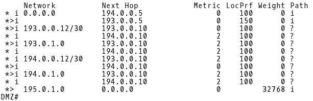
Picture 10: BGP Table of Router DMZ
The path via 193.0.0.10 (R1) to prefixes 193.0.1.0 and 194.0.1.0 is preferred to the path via 194.0.0.10 because the Router-ID 193.0.0.10 (R1) is lower than Router-ID 194.0.0.10 (R2). The route 195.0.1.0 is originated locally. The default weight for locally originated routes is 32768.
Let’s inspect the BGP table of CE-1. CE-1 contains a full Internet routing table size, simulated by the 11.0.0.0/16 and 12.0.0.0/16 networks and received from the 193.0.0.1 (ISP-A) peer (Picture 11).
CE-1# show ip bgp
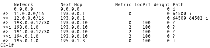
Picture 11: BGP Table of CE-1
Similarly, the router CE-2 receives the 12.0.0.0/16 and 11.0.0.0/16 routes from the 194.0.0.1(ISP-B) peer (Picture 12).
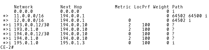
Picture 12: BGP Table of CE-2
As the last step of our verification, we will examine the BGP tables of both ISPs. (Picture 13 and 14).
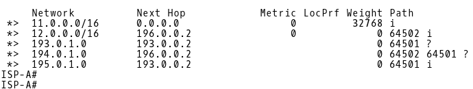
Picture 13: BGP Table of ISP-A
ISP-A learns the DMZ route 195.0.1.0 from the 193.0.0.2 (CE-1) peer (Picture 13). ISP-B, however receives the same route from two sources – 196.0.0.1 (ISP-A) and 194.0.0.2 (CE-2). (Picture 14). The path via ISP-A is being installed into the routing table of ISP-B because a path with the shortest AS_PATH is preferred. The requirement is to forward inbound traffic from the Internet to DMZ via CE-1 when a link between CE-1 and ISP-A is active and via CE-2 when the link is down. Therefore, we have configured CE-2 to prepend as-path three times with its own AS 64501 for the route 195.0.1.0/24, advertised to ISP-B.
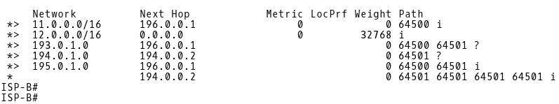
Picture 14: BGP Table of ISP-B
We will bring down the session between CE-1 and ISP-A and shutdown the interface Gi0/0 on CE-1.
CE-1(config)# interface gigabitEthernet 0/0
CE-1(config-if)# shutdown
Let’s check a routing table of the R-NAT router (Picture 15). R-NAT has installed OSPF E2 external route with a route metric 30 and the next-hop 194.0.0.13 (R1) into its routing table. It is the expected behavior as the backup path nat-south-internet is used for outgoing traffic when CE-1 (AS64501) loses eBGP session with ISP-A (AS64500).

Picture 15: Default Route via R1 Installed in RT of R-NAT
Issue the traceroute command from R-NAT to ISP-B (Picture 16) and check the NAT translation table (Picture 17).
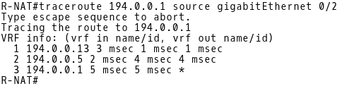
Picture 16: Traceroute from R-NAT to ISP-B
The inside local 172.16.0.1 is being translated to the same inside global address 194.0.1.3 from the NAT pool ISP-B (194.0.1.0/24) (Picture 17). The PAT (NAT overload) is in use.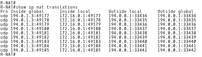
Picture 17: NAT Translation Table of R-NAT
To see how the inbound traffic is routed from the Internet to AS64501, we will check the BGP table of ISP-A (Picture 18).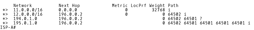
Picture 18: BGP Table of ISP-A
There are routes 194.0.1.0/24 (NAT pool ISP-B) and 195.0.1.0/24 (DMZ) installed into the BGP table of ISP-A with the next-hop 196.0.0.2 (ISP-B). The route 193.0.1.0/24 (NAT pool ISP-A) is not installed but we do not need it. The inside local addresses are translated to the ISP-B NAT pool.
R1 router redistributes a default route via OSPF conditionally, when a default route 0.0.0.0 via the next-hop 193.0.0.5 (CE-1) is installed into its routing table. But how does the R1 learn about a default route when the route is not advertised from CE-1 to R1? Remember, a link between CE-1 and ISP-A is still down. R1 installed the E2 OSPF default route received from its OSPF neighbor 193.0.0.14 (R-NAT), with a metric 30 (Picture 19).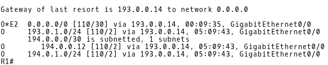
Picture 19: Default Route on R1 Received from R-NAT
Let’s bring the interface Gi0/0 on CE-1 up. The default route 0.0.0.0 via the the next-hop 193.0.0.13 (R1) is reinstalled into the routing table of R-NAT (Picture 20). The source IP addresses of outgoing traffic from the inside network to the Internet are translated to the ISP-A NAT pool again.
Picture 20: Default Route via R1 Installed in RT of R-NAT
As soon as R1 receives a default route via iBGP from CE-1, it installs it into its routing table and the OSPF default route via R-NAT is purged (Picture 21). But why are the iBGP routes with the Administrative Distance (AD) 200 preferred over the OSPF route with the distance 110? Remember, we have changed the default AD 200 for iBGP learned routes to 105 in the configuration of R1? Therefore, iBGP routes are preferred over OSPF routes as iBGP AD is set to 105. As a result, outgoing traffic is routed via ISP-A when a link between CE-A and ISP-A is active.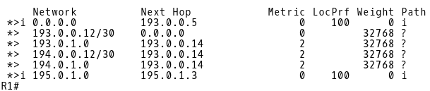
Picture 21: BGP Table of R1

Diagram 2: Enterprise Network (AS64501) is Multi-homed to ISP-A and ISP-B
In this tutorial we have covered the configuration of a multi-homed network design where a customer is connected to two different ISPs. The design ensures continuous connectivity, eliminating ISP as a single point of failure. When a primary connection to ISP-A is lost, customer traffic is routed via a backup link to ISP-B. We have also implemented the mechanism where source addresses of the internal users are translated to a different NAT address pool based on the selected path to the ISP.