Border Gateway Protocol (BGP) is not merely a protocol—it’s the backbone of the...

To better understand MPLS-TP, it is essential to explore its origins. MPLS is a packet transport technology used to establish communication paths in a network using IP routing to discover network topology. Once the topology has been discovered, signaling is used to establish communication paths, and data transfer takes place using label switching. This process can be compared to traveling from Lisbon to Helsinki, where there are numerous paths to traverse between the two points. In an MPLS network, these paths are unidirectional, meaning we would have a set of LSPs to traverse from Lisbon to Helsinki and a different set of LSPs to traverse from Helsinki to Lisbon (Figure 1).
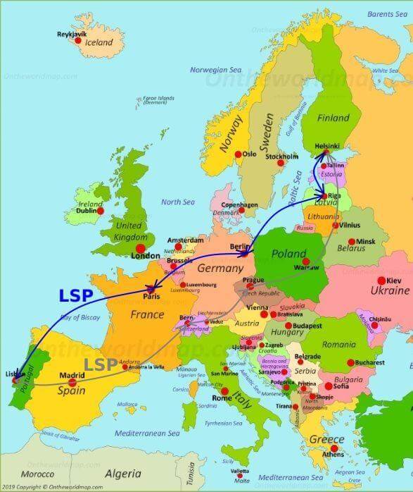
Figure 1 – Different set of LSPs for Forwarding and Reverse Paths in IP/MPLS
MPLS-TP, on the other hand, guarantees that these paths are congruent, meaning that they will traverse every segment of the network both in the forward and reverse directions (Figure 2). In contrast, in an MPLS network, these paths are non-congruent, and return traffic can pass through a completely different set of routers/nodes than the forward traffic.
To further demonstrate the advantages of MPLS-TP, let’s continue with the Lisbon to Helsinki analogy. Imagine that you’re traveling from Lisbon to Helsinki and encounter severe weather conditions in Berlin, which disrupt your journey. In a non-congruent network, you would be unable to communicate with your colleague back in Lisbon to inform them of the situation and suggest an alternative route. However, with MPLS-TP’s guaranteed congruent paths, you can communicate back to the source and provide instructions on which alternate route to take. This is possible because MPLS-TP LSPs are bidirectional and provide deterministic paths, with the forward and reverse traffic passing through the same set of routers/nodes and experiencing the same levels of delay and jitter.

Figure 2 – Same Forwarding and Reverse Paths in MPLS-TP
While congruency is a key difference between MPLS and MPLS-TP, there are other notable differences to consider. MPLS-TP uses MPLS as its foundation but applies constraints and eliminates some of the complex functions that can make networks unpredictable and non-deterministic.
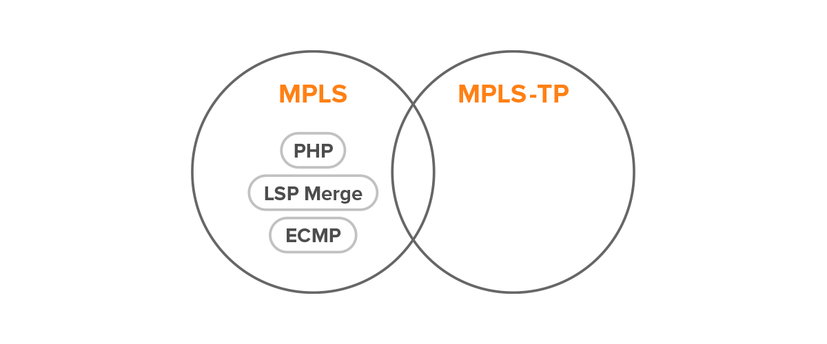
Figure 3 – Missing Features in MPL-TP
One of the functions that MPLS-TP does not support is Penultimate Hop Popping (PHP). This technique involves removing the outer label of an LSP at the penultimate hop before the egress Label Edge Router (LER) to improve performance. However, this can result in the loss of source information, making it unsuitable for MPLS-TP.
Another function that is not available in MPLS-TP is the LSP merge. In a traditional MPLS network, multiple LSPs can converge onto one outgoing LSP at a particular network element. However, this can also result in the loss of source information, and the paths are not deterministic. Therefore, LSP merge is not suitable for MPLS-TP.
MPLS-TP also does not support Equal Cost Multipath (ECMP), a common feature in IP/MPLS networks. ECMP involves load-balancing traffic flows over multiple routers that have equal cost. However, this approach is not deterministic and can lead to suboptimal routing. Therefore, MPLS-TP avoids using ECMP to ensure that network paths are predictable and deterministic.
By eliminating some of these complex functions, MPLS-TP provides a more deterministic and predictable network environment than traditional MPLS networks. Additionally, MPLS-TP adds carrier-grade Operation, Administration, and Maintenance (OAM) capabilities, which provide fault management, performance management, and network visibility. These features make MPLS-TP well-suited for use in carrier networks, where reliability and predictability are paramount.
In fact, MPLS-TP can be expressed in a single formula:
MPLS-TP = MPLS + OAM – IP
OAM (Operations, Administration, and Maintenance) is an important feature in telecommunications networks that allows operators to monitor and manage the health and performance of their networks.
In the context of MPLS-TP, OAM is achieved using special-purpose packets called Generic Associated Channel (G-ACh) messages, which are carried in the payload of MPLS-TP packets. G-ACh messages are used to carry OAM information and are identified by a special G-ACh header carried in the MPLS-TP packet.
This example showcases the configuration of MPLS Transport Profile (MPLS-TP) for sending and receiving OAM GAL and G-Ach messages through an LSP on Juniper vMX routers (Figure 4). It also demonstrates how to associate two unidirectional RSVP LSPs between a pair of routers to create an associated bidirectional LSP for binding a path for the GAL and G-Ach OAM messages.

Figure 4 – Network Topology
Note: An MPLS router that performs routing based only on the label is called a label switch router (LSR) or transit router. This type of router is located in the middle of an MPLS network. It is responsible for switching the labels used to route packets.
A label edge router (LER, also known as edge LSR) is a router that operates at the edge of an MPLS network and acts as the entry and exit points for the network. LERs push an MPLS label onto an incoming packet and pop it off an outgoing packet.
Note: This example shows the configuration on R0 and R4 ingress/egress router and the transit router R1. Repeat the configuration for other transit routers.
Configure Interfaces:
root@R0# set interfaces ge-0/0/1 unit 0 family inet address 10.10.10.1/30
root@R0# set interfaces ge-0/0/1 unit 0 family mpls
root@R0# set interfaces ge-0/0/2 unit 0 family inet address 10.10.9.1/30
Configure MPLS on interfaces:
root@R0# set protocols mpls interface ge-0/0/1.0
Configure OSPF:
root@R0# set protocols ospf traffic-engineering
root@R0# set protocols ospf area 0.0.0.0 interface ge-0/0/1.0
root@R0# set protocols ospf area 0.0.0.0 interface ge-0/0/2.0
root@R0# set protocols ospf area 0.0.0.0 interface lo0.0 passive
Configure signaling protocol – RSVP:
root@R0# set protocols rsvp interface ge-0/0/1.0
Configure LSP:
root@R0# set protocols mpls label-switched-path r0-to-r4 to 10.255.1.2
Enable GAL and G-Ach OAM operation without IP encapsulation on the LSPs:
root@R0# set protocols mpls label-switched-path r0-to-r4 oam mpls-tp-mode
Configure associated bidirectional LSPs on the two ends of the LSP:
root@R0# set protocols mpls label-switched-path r0-to-r4 associate-lsp r4-to-r0 from 10.255.1.2
Configure Interfaces:
root@R1# set interfaces ge-0/0/1 unit 0 family inet address 10.10.10.2/30
sroot@R1# set interfaces ge-0/0/1 unit 0 family mpls
root@R1# set interfaces ge-0/0/2 unit 0 family inet address 10.10.11.1/30
root@R1# set interfaces ge-0/0/2 unit 0 family mpls
root@R1# set interfaces ge-0/0/3 unit 0 family inet address 10.10.12.1/30
root@R1# set interfaces ge-0/0/3 unit 0 family mpls
Configure MPLS on interfaces:
root@R1# set protocols mpls interface ge-0/0/1.0
root@R1# set protocols mpls interface ge-0/0/2.0
root@R1# set protocols mpls interface ge-0/0/3.0
Configure OSPF:
root@R1# set protocols ospf traffic-engineering
root@R1# set protocols ospf area 0.0.0.0 interface ge-0/0/1.0
root@R1# set protocols ospf area 0.0.0.0 interface ge-0/0/2.0
root@R1# set protocols ospf area 0.0.0.0 interface ge-0/0/3.0 metric 100
root@R1# set protocols ospf area 0.0.0.0 interface lo0.0 passive
Configure signaling protocol – RSVP:
root@R1# set protocols rsvp interface ge-0/0/1.0
root@R1# set protocols rsvp interface ge-0/0/2.0
root@R1# set protocols rsvp interface ge-0/0/3.0
Configure the association of the two LSPs on the transit router:
root@R1# set protocols mpls transit-lsp-association trace1 lsp-name-1 r0-to-r4
root@R1# set protocols mpls transit-lsp-association trace1 from-1 10.255.1.1
root@R1# set protocols mpls transit-lsp-association trace1 lsp-name-2 r4-to-r0
root@R1# set protocols mpls transit-lsp-association trace1 from-2 10.255.1.2
Configure Interfaces:
root@R4# set interfaces ge-0/0/1 unit 0 family inet address 10.10.14.1/30
root@R4# set interfaces ge-0/0/1 unit 0 family mpls
root@R4# set interfaces ge-0/0/2 unit 0 family inet address 10.10.15.1/30
Configure MPLS on interfaces:
root@R4# set protocols mpls interface ge-0/0/1.0
Configure OSPF:
root@R4# set protocols ospf traffic-engineering
root@R4# set protocols ospf area 0.0.0.0 interface ge-0/0/1.0
root@R4# set protocols ospf area 0.0.0.0 interface ge-0/0/2.0
root@R4# set protocols ospf area 0.0.0.0 interface lo0.0 passive
Configure signaling protocol – RSVP:
root@R4# set protocols rsvp interface ge-0/0/1.0
Configure LSP:
root@R4# set protocols mpls label-switched-path r4-to-r0 to 10.255.1.1
Enable GAL and G-Ach OAM operation without IP encapsulation on the LSPs:
root@R4# set protocols mpls label-switched-path r4-to-r0 oam mpls-tp-mode
Configure associated bidirectional LSPs on the two ends of LSP:
root@R4# set protocols mpls label-switched-path r4-to-r0 associate-lsp r0-to-r4 from 10.255.1.1
Verify that the associated bidirectional LSP configuration is working properly (Figures 5 and 6).
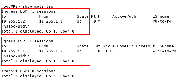
Figure 5 – Checking MPLS LSPs on R0 Ingress Router
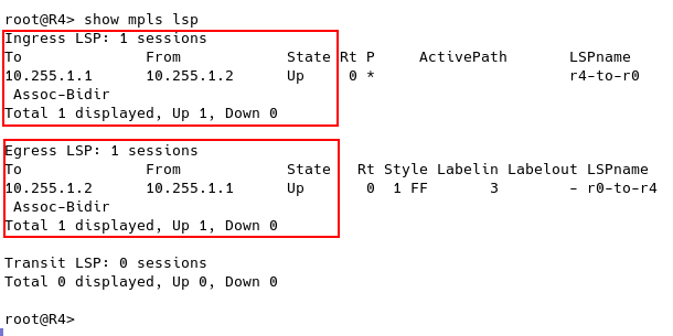
Figure 6 – Checking MPLS LSPs on R4 Egress Router
To wrap up, MPLS-TP is a carrier-grade transport platform well-suited for edge, aggregation, and access networks, while IP/MPLS is appropriate for the core. MPLS-TP provides the predictability and reliability of circuit-based transport networks, making it an attractive option for carriers who require a deterministic transport solution. Additionally, MPLS-TP is fully compatible with IP/MPLS networks, which opens up numerous possibilities for network solutions that require MPLS/MPLS-TP interworking.
MPLS-TP aims to replace legacy networks such as SONET/SDH while retaining the advantages of packet transport. By eliminating some of the complex functions that make networks unpredictable and non-deterministic, MPLS-TP provides a more predictable and deterministic network environment. With carrier-grade OAM capabilities, MPLS-TP offers fault management, performance monitoring, and network visibility, making it a reliable and robust transport solution for carrier networks.
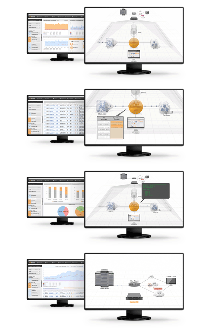
Automate BGP Routing optimization with Noction IRP
In recent years, the concepts of Artificial Intelligence (AI) and Machine Learning (ML) have moved from the academic...
Recent disruptions to two undersea internet cables in the Baltic Sea have yet again highlighted a pressing issue for...
Understanding BGP states is essential to grasp how BGP operates. Similar to interior gateway protocols (IGPs) like...