Border Gateway Protocol (BGP) is not merely a protocol—it’s the backbone of the...


Virtual Routing and Forwarding (VRF) is a Layer-3 virtualization technique used to virtualize routing tables so multiple routing tables can exist in one physical router and work simultaneously. Each VRF has its own Layer-3 forwarding table. Any device in a specific VRF can be Layer-3 directly routed to another device in the same VRF, but cannot directly reach one in another VRF. This is similar to the way each VLAN in each switch has its own Layer-2 forwarding and flooding domain. Any device in a VLAN can directly reach another device at Layer-2 in the same VLAN, but not a device in another VLAN unless it is forwarded by a Layer-3 router [1]. VRFs employ essentially the same concept as VLANs and trunking, but at layer three. Similar to the VLAN configuration on the switch where each access (switched) port is assigned to a specific VLAN, VRF is assigned to Layer-3 (routed) interface on the router. As VRF is a Layer-3 virtualization technique we also need to define routes with their particular next-hops to VRFs.
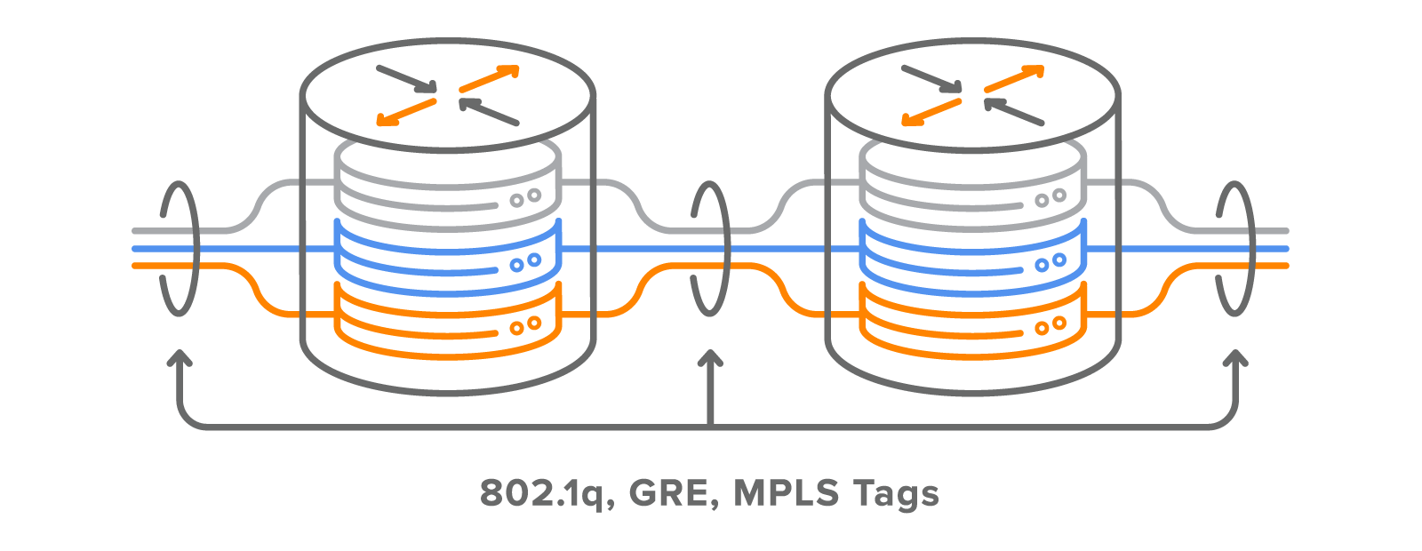
Just as with a VLAN based network using 802.1q trunks to extend the VLAN between switches, a VRF based design uses 802.1q trunks, GRE tunnels, or MPLS tags to extend and tie the VRFs together. This is depicted in Picture 1. As traffic is automatically segregated, VRF increases network security and can eliminate the need for encryption and authentication. Internet service providers (ISPs) often take advantage of VRF to create separate virtual private networks (VPNs) for customers thus the technology is also referred to as VPN routing and forwarding [2]. In these networks, MPLS encapsulation is used to isolate individual customers’ traffic and an independent routing table (VRF) is maintained for each customer. The Multi-Protocol BGP (MP-BGP) is employed in an MPLS network to import and export routes to and from VRFs.

Figure 1: Different Approaches to Extend VRF IDs Outside Campus Network.
Source: https://www.cisco.com/c/en/us/td/docs/solutions/Enterprise/Campus/campover.html#wp709341
[wc_divider style=”solid” line=”single” margin_top=”” margin_bottom=””]
| Note: You can learn more about BGP/MPLS Layer-3 VPNs terminology, principles and benefits by reading the Noction blog. There is also a tutorial with the exact configuration steps that you can use to build your own BGP/MPLS Layer-3 VPN network topology. |
Although VRF is closely tied with MPLS, VRFs can segment networks without the use of MPLS and MP-BGP. Therefore, no route-target is required as a part of the configuration in order to import and export routes from and to VRF. VRF Cisco without the MPLS is known as VRF Lite. It is used for the isolation in an enterprise LAN, data centers, etc.
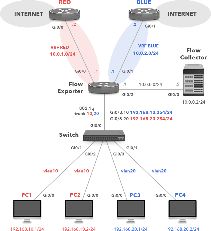
Assume a single network topology depicted in Picture 2. The company has two links to the Internet. Trusted traffic from the corporate VLAN 20 to the Internet must pass through the firewall on the right so that the company policy can be enforced. The second Internet access is designated for guests visiting the company campus. The network 192.168.10.0/24 (VLAN 10) is used for guest traffic and 192.168.20.0/24 (VLAN 20) is used for corporate traffic. VFR is employed to segment a single physical infrastructure into two virtual, isolated networks. Thanks to this concept, packets from the guest network (VRF RED) cannot move to the trusted network (VRF BLUE) and vice versa. Packets entering VRF RED can only follow routes in the RED routing table. Similarly, packets entering VRF BLUE can only follow routes in the BLUE routing table. As a result, no traffic can pass between the guest and corporate VLANs. Both VLANs are mapped to the particular VRF router (or a Layer-3 device).

Figure 2: Enterprise Network with VRF Lite Configuration.
[wc_divider style=”solid” line=”single” margin_top=”” margin_bottom=””]
The company policy requires to collect VRF IDs as keys for traffic sent from both guest and corporate networks to the Internet. Therefore, the router named Flow_Exporter is configured to collect and export NetFlow v9 records to the Flow collector 10.0.0.2/24. Flows are exported from the router’s flow cache as UDP datagrams based on either the active or inactive timeouts. For instance, flow is exported when it is inactive for a certain time e.g. no new packets are received for the flow. By default, the inactive flow timer is set to 15 seconds. The flow is also exported when it is long-lived (active) and lasts longer than the active timer. By default, the active timer is set to 30 minutes. For example, a large file download that lasts longer than 30 minutes may be broken into multiple flows. It is the role of the flow collector to combine these flows showing a total download. The role of the collector is gathering, recording, combining or aggregating the exported flows to produce the reports used for traffic and security analysis.
Traditional NetFlow v5 uses a 7-tuple of source and destination IP addresses, source and destination transport layer port numbers, IP Protocol, Type of Service (ToS), and source interface. Each packet that is going to be forwarded is examined for the above parameters. The first unique packet creates a flow as an entry in NetFlow cache (flow record). The packets are then forwarded out of the router. The other packets matching the same parameters are aggregated to this flow and the bytes counter for the flow increases. If any of the parameters are not matched, a new flow is created in the router’s flow cache.
Obviously, NetFlow v5 is locked in terms of fields that can be matched and exported, so we cannot use it to collect VRF IDs. NetFlow v9, however, is template based so we can choose the fields that should be presented in the exported flows. For instance, we can collect NetFlow records based on Layer-2 information or VRF IDs. The template is periodically sent to the NetFlow collector telling it what data to expect from the router.
The Flexible NetFlow (FnF) is the configuration interface on the router or switch which allows the user to take advantage of NetFlow v9, allowing users to configure and customize what information is exported in flow records. FnF is perfectly suited to collect VRF IDs required by the company’s security policies. In general, Flexible NetFlow consists of 3 components. We will provide configuration steps for each of the components with detailed explanation in part 1.
1) Flow Record
2) Flow Exporter
3) Flow Monitor
The Flexible NetFlow – Ingress VRF Support feature enables collecting VRF IDs from incoming packets on the router by applying an input flow monitor having a flow record that collects the VRF ID as a key or a nonkey field. The FnF – Egress VRF Support feature enables collecting the virtual routing and forwarding (VRF) ID from the outgoing packets on a router by applying an output flow monitor having a flow record that collects the VRF ID as a key or a nonkey field. NetFlow v9 gives us the capability to collect VRF IDs either in ingress or egress direction. In general, the egress flow collection is mostly used when a device compresses data. In this case, the difference between the measured bytes in ingress and egress direction may be significant so the egress flow collection is used for more accurate results. As the router NetFlow_Exporter is not involved in compression, we will collect flow records in the ingress direction. We are going to collect incoming packets on the subinterfaces GigabitEthernet0/3.10 and GigabitEthernet0/3.20.
First, we will create two VRF instances. The VRF instance RED is designated for guest traffic and the VRF instance BLUE is for the corporate traffic.
NetFlow-exporter(config)# ip vrf RED
NetFlow-exporter(config-vrf)# ip vrf BLUE
NetFlow-exporter(config-vrf)# exit
Each routed interface, whether it is physical or virtual, belongs to exactly one VRF.
Flow-exporter(config)# interface GigabitEthernet0/0
Flow-exporter(config-if)# ip vrf forwarding RED
Flow-exporter(config-if)# ip address 10.0.1.1 255.255.255.0
Flow-exporter(config-if)# no shutdown

Flow-exporter(config)# interface GigabitEthernet0/1
Flow-exporter(config-if)#  ip vrf forwarding BLUE
Flow-exporter(config-if)# ip address 10.0.2.1 255.255.255.0
Flow-exporter(config-if)# no shutdown

Flow-exporter(config)# interface GigabitEthernet0/2
Flow-exporter(config-if)# description Export to Flow collector
Flow-exporter(config-if)# ip address 10.0.0.1 255.255.255.0
Flow-exporter(config-if)# no shutdown

Flow-exporter(config)# interface GigabitEthernet0/3
Flow-exporter(config-if)# no ip address
Flow-exporter(config-if)# exit
The interface GigabitEthernet0/3 provides transport for guest and corporate traffic. Therefore, we are going to configure it with two subinterfaces performing 802.1Q encapsulation. The IEEE 802.1Q VLAN ID 10 for VLAN 10 (RED) and .20 for VLAN 20 (BLUE). Although 802.1Q encapsulation is used to tag frames across the link, each link is a routed segment with an IP interface at either end.
Flow-exporter(config)# interface GigabitEthernet0/3.10
Flow-exporter(config-if)#  encapsulation dot1Q 10
Flow-exporter(config-if)#  ip vrf forwarding RED
Flow-exporter(config-if)#  ip address 192.168.10.254 255.255.255.0
Flow-exporter(config-if)#  no shutdown
Flow-exporter(config-if)# exit

Flow-exporter(config)# interface GigabitEthernet0/3.20
Flow-exporter(config-if)#  encapsulation dot1Q 20
Flow-exporter(config-if)#  ip vrf forwarding BLUE
Flow-exporter(config-if)#  ip address 192.168.20.254 255.255.255.0
Flow-exporter(config-if)#  no shutdown
Flow-exporter(config-if)# exit
We also need to configure static default routes for both VPN Routing/Forwarding instances so hosts in guest and corporate networks can reach the Internet.
Flow-exporter(config)# ip route vrf RED 0.0.0.0 0.0.0.0 10.0.1.2
Flow-exporter(config)# ip route vrf BLUE 0.0.0.0 0.0.0.0 10.0.2.2
Now, check the global routing table for connected routes (Picture 3).

Figure 3: Global Routing Table with Connected Route 10.0.0.0/24.
[wc_divider style=”solid” line=”single” margin_top=”” margin_bottom=””]
To display routes from a VPN Routing/Forwarding instance RED, we need to add vrf keyword and the VRF name to the ip route command (Picture 4). The connected networks 10.0.1.0/24 and 192.168.10.0./24 along with a static default route with the next-hop IP address 10.0.1.2 (the router RED) reside in the VRF RED table.

Figure 4: VRF RED Table.
[wc_divider style=”solid” line=”single” margin_top=”” margin_bottom=””]
To display the content of the BLUE VRF table, replace the vrf argument and the RED value with the BLUE value (Picture 5). The table contains connected routes 10.0.2.0/24 and 192.168.20.0./24 along with a static default route with the next-hop 10.0.2.2 (the BLUE router).

Figure 5: Number of Demands Related to Various Traffic Sources and Destinations.
[wc_divider style=”solid” line=”single” margin_top=”” margin_bottom=””]
The Flow Record serves as the basis for the NetFlow template used in the export process by specifying the information that we want to collect. The template contains key fields that are matched with a match statement and non-key fields matched with the collect statements. All the key-fields matched with the match statement are collected as well. Just as with the traditional NetFlow v5 we match 7-tuple key fields with the match statements. If one of the incoming packets does not match a key field in the flow cache, a new flow is made. In addition, Flexible NetFlow (FnF) allows defining additional matching key fields such as VRF routing attributes and many others. In our example, virtual routing and forwarding (VRF) IDs are matched as the key-fields from the incoming packets.
We also collect additional information that will be added to the Flow Record. This information is named non-key fields that are specified with the collect statement. The non-key fields are not used to create or characterize the flows. They are only exported with the flow. In our case, non-key fields that we collect include interface output, packet, bytes counters and timestamps.
Flow-exporter(config)# flow record VRF_RECORD
Flow-exporter(config-flow-record)# match ipv4 source address
Flow-exporter(config-flow-record)# match ipv4 destination address
Flow-exporter(config-flow-record)# match transport source-port
Flow-exporter(config-flow-record)# match transport destination-port
Flow-exporter(config-flow-record)# match ipv4 protocol
Flow-exporter(config-flow-record)# match ipv4 tos
Flow-exporter(config-flow-record)# match interface input
Flow-exporter(config-flow-record)# match routing vrf input
Flow-exporter(config-flow-record)# collect interface output
Flow-exporter(config-flow-record)# collect counter packets
Flow-exporter(config-flow-record)# collect counter bytes
Flow-exporter(config-flow-record)# collect timestamp sys-uptime first
Flow-exporter(config-flow-record)# collect timestamp sys-uptime last
Flow-exporter(config-flow-record)# exit
The Flow Exporter defines where to send the NetFlow data. Create a new Flow Exporter VRF_EXPORTER and specify the IP address and the UDP port of the NetFlow collector, the interface used for the flow export and the timeout for template export in seconds.
Flow-exporter(config)# flow exporter VRF_EXPORTER
Flow-exporter(config-flow-exporter)# description Flexible NetFlow version 9
Flow-exporter(config-flow-exporter)# destination 10.0.0.2
Flow-exporter(config-flow-exporter)# source GigabitEthernet0/2
Flow-exporter(config-flow-exporter)# transport udp 2055
Flow-exporter(config-flow-exporter)# template data timeout 60
The Flow Monitor defines the flow record we want to use as well as the associated parameters (number of cache entries, when to flush the cache etc). We define the Flow Exporter here as well. Create a new Flow Monitor VRF_MONITOR. Assign the flow record VRF_RECORD and the Flow Exporter VRF_EXPORTER to the Flow Monitor.
Flow-exporter(config)# flow monitor VRF_MONITOR
Flow-exporter(config-flow-monitor)# description VRF Monitor
Flow-exporter(config-flow-monitor)# exporter VRF_EXPORTER
Flow-exporter(config-flow-monitor)# record VRF_RECORD
Flow-exporter(config-flow-monitor)# cache timeout active 30
Finally, let’s apply the Flow Monitor to the interface on which we want to perform NetFlow collection. Apply the Flow Monitor VRF_MONITOR to input traffic for both of the sub-interfaces.
Flow-exporter(config)# interface GigabitEthernet 0/3.10
Flow-exporter(config-subif)# ip flow monitor VRF_MONITOR input

Flow-exporter(config)# interface GigabitEthernet 0/3.20
Flow-exporter(config-subif)# ip flow monitor VRF_MONITOR input
The configuration of the Layer-2 switch is pretty straightforward. All we need to do is to create VLANs 10 and 20, define a port GigabitEthernet0/0 as a trunk port and assign the ports GigabitEthernet0/1 – 3 and GigabitEthernet1/0 to VLANs.
Switch(config)# interface GigabitEthernet 0/3
Switch(config-if)# switchport trunk encapsulation dot1q
Switch(config-if)# switchport mode trunk
Switch(config-if)# switchport trunk allowed vlan 10,20
Switch(config-if)# exit

Switch(config)# interface range GigabitEthernet 0/1 - 2
Switch(config-if-range)# switchport mode access
Switch(config-if-range)# switchport access vlan 10
Switch(config-if-range)# exit

Switch(config)# interface range GigabitEthernet 0/3, GigabitEthernet 1/0
Switch(config-if-range)# switchport mode access
Switch(config-if-range)# switchport access vlan 20
Switch(config-if-range)#  exit
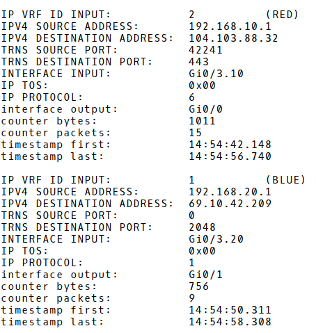
The first two flow records stored in a flow cache of the router Flow-Exporter are shown in Picture 6. The first record represents TCP traffic (IP protocol 6), from the IP address 192.168.10.1 (PC1 in guest VLAN 10), source TCP port 42241 sent to the IP address 104.103.88.32 (cisco.com), destination TCP port 443 (application protocol HTTPS). The VRF ID RED is attached as we have specified VRF collection with the match statement under the flow record configuration. There are 15 sent packets with the counter bytes equal to 1011.
The second flow record represents ICMP traffic sent from the host PC3 – IP 192.168.20.1/24 assigned to the corporate VLAN 20 to an IP address 69.10.42.209 (usa.com). The VRF ID – BLUE is attached as well.
Flow-exporter# show flow monitor VRF_MONITOR cache

Figure 6: Content of Flow Cache with First Two Records.
[wc_divider style=”solid” line=”single” margin_top=”” margin_bottom=””]
Flexible Netflow provides the ability to characterize IP traffic and identify its source, destination, timing, and application information critical for network availability, performance, and troubleshooting. Flexible NetFlow is able to export flow records using NetFlow v5 so customers can easily migrate from traditional NetFlow to Flexible NetFlow without impacting existing NetFlow collectors. However, updating legacy flow collectors is essential if customers want to take advantage of all the flexibility that Flexible NetFlow provides, such as collecting VRF identifiers, Layer-2 MAC addresses, VLANs IDs, and more.