We are excited to announce the release of NFA 24.04, which introduces significant...


Request a personalized demo/review session of our Intelligent Routing Platform

Evaluate Noction IRP, and see how it meets your network optimization challenges

Schedule a one-on-one demonstration of our network traffic analysis product

Test drive NFA today with your own fully featured 30-day free trial
 Understanding BGP states is essential to grasp how BGP operates. Similar to interior gateway protocols (IGPs) like EIGRP, OSPF, or ISIS, BGP establishes peering with other routers before exchanging routing information. However, unlike IGPs, BGP does not utilize broadcast or multicast for neighbor discovery. Instead, neighbors are manually configured and BGP leverages TCP Port 179 to establish a reliable connection with neighboring BGP speakers. This allows for communication between BGP neighbors across any distance as long as TCP connectivity exists.
When routers are configured as BGP neighbors with each other’s IP address, one router functions as a TCP server while the other acts as a client, depending on which router initiates the connection. In the process of establishing a connection between a TCP client and server, the client initiates the connection by sending a TCP SYN packet to the server using the well-known port as the destination. This SYN serves as a request to open a session. If the server approves the session, it responds with a TCP SYN-ACK, indicating acknowledgment of the request and a desire to open the session. This response uses the well-known port as the source port and a randomly negotiated destination port. The final step of this three-way handshake is the client sending a TCP ACK to the server, acknowledging its response and completing the connection establishment.
The process is similar in the context of BGP, where routers act as TCP clients and servers. Let’s illustrate this with an example depicted in Figure 1. The router with the IP address 10.0.0.1 initiates the BGP session using TCP protocol moving from the Idle to Connect state of the BGP session, However, prior to sending any BGP message, a 3-way TCP handshake must be completed. The router initiating the handshake becomes the TCP client. The client sends a request (SYN packet) to the server, which is a BGP neighbor configured with the destination IP address 10.0.0.2. Syn packet is sent to port 179 with a randomly assigned source port 21888.
Understanding BGP states is essential to grasp how BGP operates. Similar to interior gateway protocols (IGPs) like EIGRP, OSPF, or ISIS, BGP establishes peering with other routers before exchanging routing information. However, unlike IGPs, BGP does not utilize broadcast or multicast for neighbor discovery. Instead, neighbors are manually configured and BGP leverages TCP Port 179 to establish a reliable connection with neighboring BGP speakers. This allows for communication between BGP neighbors across any distance as long as TCP connectivity exists.
When routers are configured as BGP neighbors with each other’s IP address, one router functions as a TCP server while the other acts as a client, depending on which router initiates the connection. In the process of establishing a connection between a TCP client and server, the client initiates the connection by sending a TCP SYN packet to the server using the well-known port as the destination. This SYN serves as a request to open a session. If the server approves the session, it responds with a TCP SYN-ACK, indicating acknowledgment of the request and a desire to open the session. This response uses the well-known port as the source port and a randomly negotiated destination port. The final step of this three-way handshake is the client sending a TCP ACK to the server, acknowledging its response and completing the connection establishment.
The process is similar in the context of BGP, where routers act as TCP clients and servers. Let’s illustrate this with an example depicted in Figure 1. The router with the IP address 10.0.0.1 initiates the BGP session using TCP protocol moving from the Idle to Connect state of the BGP session, However, prior to sending any BGP message, a 3-way TCP handshake must be completed. The router initiating the handshake becomes the TCP client. The client sends a request (SYN packet) to the server, which is a BGP neighbor configured with the destination IP address 10.0.0.2. Syn packet is sent to port 179 with a randomly assigned source port 21888.
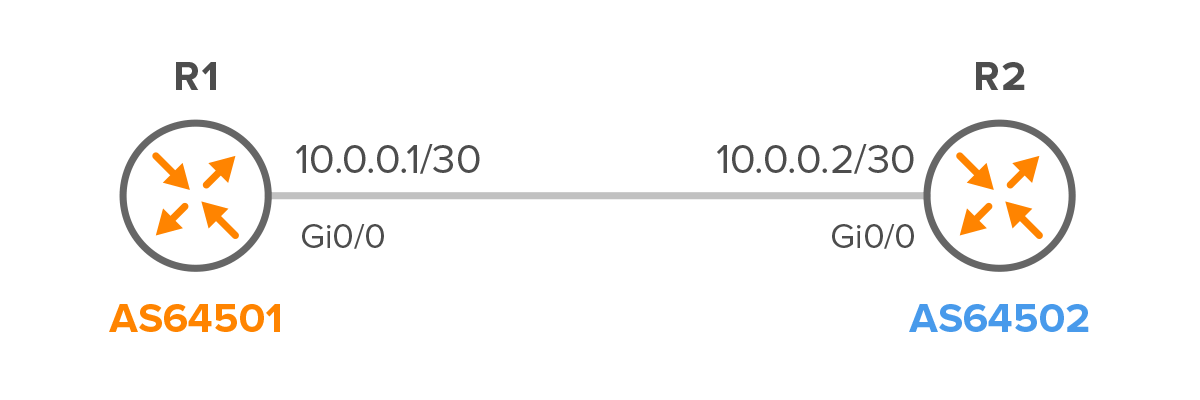
Figure 1 – R1 and R2 Configured as eBGP Neighbors
Note: Initially, the BGP session is in an Idle state, where BGP waits to start a BGP session. TCP 3-way TCP handshake occurs when the BGP session is in the Connect state.
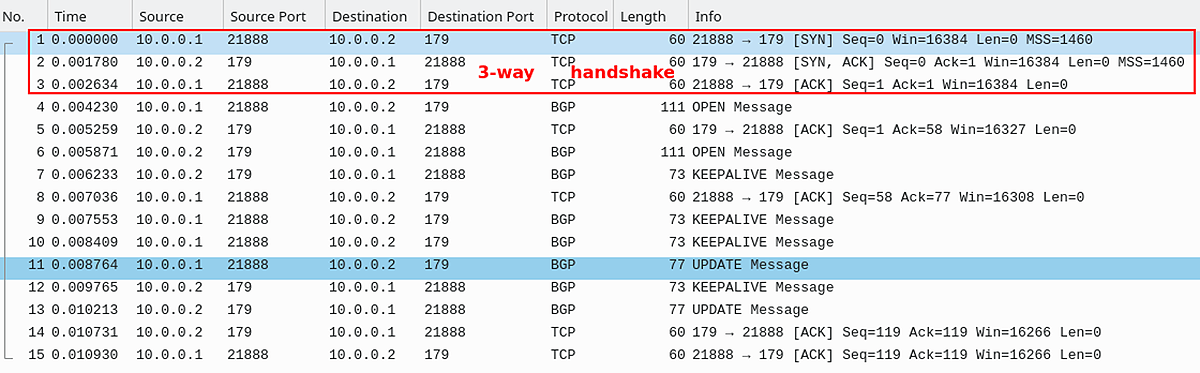
Figure 2 – BGP connection Using TCP Ports
access-list 100 permit tcp host 10.0.0.1 host 10.0.0.2 eq bgp
access-list 100 permit tcp host 10.0.0.1 eq bgp host 10.0.0.2
Once R1 and R2 have completed the TCP 3-way handshake, they proceed to exchange Open messages, transitioning the session to the OpenSent state. Subsequently, the BGP session progresses to the OpenConfirm state. In this state, routers await acknowledgment of the OPEN message along with Keepalive messages from their peers. Upon successful receipt of these messages, the session enters the Established state. In the Established state, peers engage in the exchange of UPDATE messages and routing information. This is the only state where BGP peers actively exchange routing information.
When two BGP routers aim to establish a peering relationship, one router assumes the role of the active peer, while the other takes on the passive role, similar to a client-server dynamic where the passive router acts as the server and the active router as the client. This terminology aligns with the concepts of BGP listener (server) and BGP initiator (client).
Typically, the active peer actively seeks and establishes the connection with the passive peer. Determination of which router becomes the active peer is based on their respective BGP router IDs, with the router possessing the higher ID assuming the active role. Each router knows its own router ID and can also ascertain the router ID of its neighbor through the BGP neighbor command.
Open messages are used by a router to identify itself and specify it’s operation parameters (Figure 3). An Open message contains the BGP Version number, AS number, Hold Time, BGP identifier and Optional parameters (Figure 3). BGP identifier is the same as a router-id, and is actually configured with the bgp router-id command.
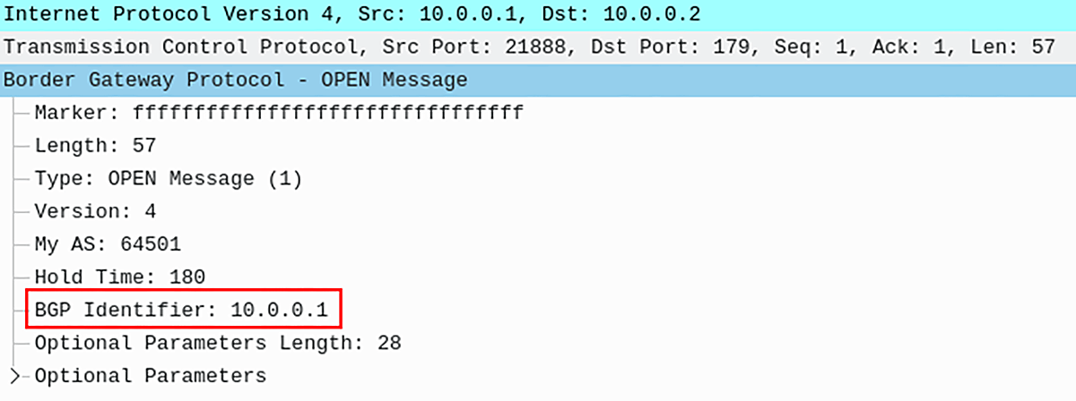
Figure 3 – BGP Open Message with BGP Identifier 10.0.0.1
Based on the value of the BGP Identifier, a convention is established for detecting which BGP connection is to be preserved when a collision occurs. The convention is to compare the BGP Identifiers of the peers involved in the collision and to retain only the connection initiated by the BGP speaker with the higher-valued BGP Identifier. In other words, higher-valued BGP identifier becomes the client and its connection is preserved.
To avoid potential collisions in establishing BGP sessions, we can explicitly determine which BGP peer should act as the server (listen on TCP port 179 and await incoming connection requests) and which should act as the client (initiate TCP handshakes to establish connections). This will ensure there will be only single TCP session between BGP peers.
router bgp 64502
   neighbor 10.0.0.1 remote-as 64501
   neighbor 10.0.0.1 transport connection-mode passive
In this configuration:
By configuring R2 in this manner, it will wait for R1 to initiate the TCP handshake, thereby avoiding any potential collision scenarios. While configuring R1 as active (initiating the TCP handshake) is optional, it can further ensure that only one TCP session is established between the BGP peers, enhancing network stability and reliability.
The command show ip bgp neighbors is executed to verify if R2 serves as the TCP connection server, as depicted in Figure 4.
R2# show ip bgp neighbors | include host

Figure 4 – Checking BGP Ports
In summary, understanding BGP states is crucial for comprehending how BGP operates. Unlike interior gateway protocols (IGPs), BGP manually configures neighbors and uses TCP port 179 for establishing reliable connections.
When two routers attempt to establish a BGP session, one becomes the client and the other the server. The client sends a TCP SYN packet to the server, and upon receiving it, the server responds with a TCP SYN-ACK packet. The routers complete a three-way handshake, and if a collision occurs, the connection initiated by the router with the higher BGP Identifier is preserved.
Configuring one router as the server and the other as the client helps avoid collisions and ensures a single TCP session between BGP peers, enhancing network stability.
Automate BGP Routing optimization with Noction IRP

The Mail Analogy: Understanding TCP Headers and Reliable Delivery The internet seamlessly transfers data, but how does...

Last week, Africa faced yet again a significant setback in its connectivity infrastructure, with multiple undersea...

The Border Gateway Protocol (BGP) serves as the lifeblood of the internet, facilitating the exchange of routing...